Su carrito de compras está vacío
 
English Polski Spanish 
Buscar un manual
 

(p.Ej. AA-V20EG JVC, ZX-7 Sony)
PayPal 1000+ rating Secure, Encrypted Checkout.
 
Usuarios conectados
Actualmente hay 5923 visitantes online.
Productos
Información
Destacado
Inicio >> CASIO >> KL8100 Manual de Servicio
 
 0 artículo(s) en Su carrito 

CASIO KL8100
Manual de Servicio


¡Twitee acerca de este producto y obtenga $1.00 de crédito en la tienda para uso!
  • Contiene diagramas del circuito
  • Descargable
  • Formato PDF
  • Manual completo
  • Idiomas: English
Precio: $4.99

Descripción del CASIO KL8100 Manual de Servicio

Manual de servicio completo en formato digital (archivo PDF). Los manuales de servicio por lo general contienen diagramas de circuitos, tarjetas de circuitos impresos, consejos para reparación, diagramas de cableado, diagramas de bloque y lista de refacciones. El Manual de Servicio (a veces llamado Manual de Reparación) es usado principalmente por los técnicos.

Si tan solo quiere saber cómo utilizar su televisión, reproductor de vídeo, reproductor de mp3, etc. Quizá lo que necesita es el Manual del Propietario. Después de colocar la orden le enviaremos las instrucciones de descarga a su dirección de e-mail.

The manual is available in languages: English

Not yet ready
You must purchase it first

Opiniones de los clientes
No hay comentarios de productos.

TEXT_PDF_SNIPPET
5. ADJUSTMENT
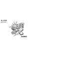
Refer to the figure in the next page and 10-2. Power supply.

5-1. Setting the thermal head
Perform this setting after removing batteries and AC adapter. After replacing the thermal head or chassis ass�y, decide to connect or not to connect RANK1 pads on the PCB ASSY with soldering according to the following table. Marking on the thermal head A B RNK1 pads connect (short) not connect (open)

5-2. Adjustment for power supply voltage to LCD
Be sure to perform this adjustment after replacing PCB ASSY, LCD, chassis ass�y and so on. 1 After supplying the voltage 12.5 V ± 2 % to SUM + terminal for battery, turn on the unit. 2 Adjusting VR1, set the voltage between CPVDD and CPV5 pads on the PCB ASSY to the voltage shown to the following table. Voltage between CPVDD and CPV5 pads Polarity: CPVDD (=VDD1) ¡ + (plus) CPV5 ¡ � (minus) 6.2 V ± 0.1 V

5-3. Adjustment for VP terminal voltage
Be sure to perform this adjustment after replacing PCB ASSY, motor, thermal head, chassis ass�y and so on. After supplying the voltage 12.5 V ± 2 % to SUM + terminal for battery, perform this adjustment while printing. Adjusting VR201, set the voltage between VP and CPD203 pads on the PCB ASSY to the voltage shown to the following table.

Voltage between VP and CPD203 Polarity: VP ¡ + (plus) CPD203 (=DGND) ¡ � (minus)

6.8 V ± 0.05 V

�8�

Quizás también quiera comprar

$4.99

KL8100 CASIO
Manual de Usuario

Manual del propietario completo en formato digital. El manual estará disponible para descarga como …
>
Parse Time: 1.153 - Number of Queries: 100 - Query Time: 0.608